The Cool Car
A Digital Embedded Systems University Project
Overview
This was a group project for the ENSC3020 unit at UWA where we (as a group of 4) had to build and program a RC car that could take in coordinates and drive to those coordinates and back to its start point by itself.
Design
Hardware Circuit Design
- Parts:
- Arduino Nano
- L298N H Bridge driver module
- GPS module
- Power pack
- Motors x4
- The arduino is connected to the driver, gps, and power pack which is all seated in a chassis which has 4 DC motors connected to wheels.
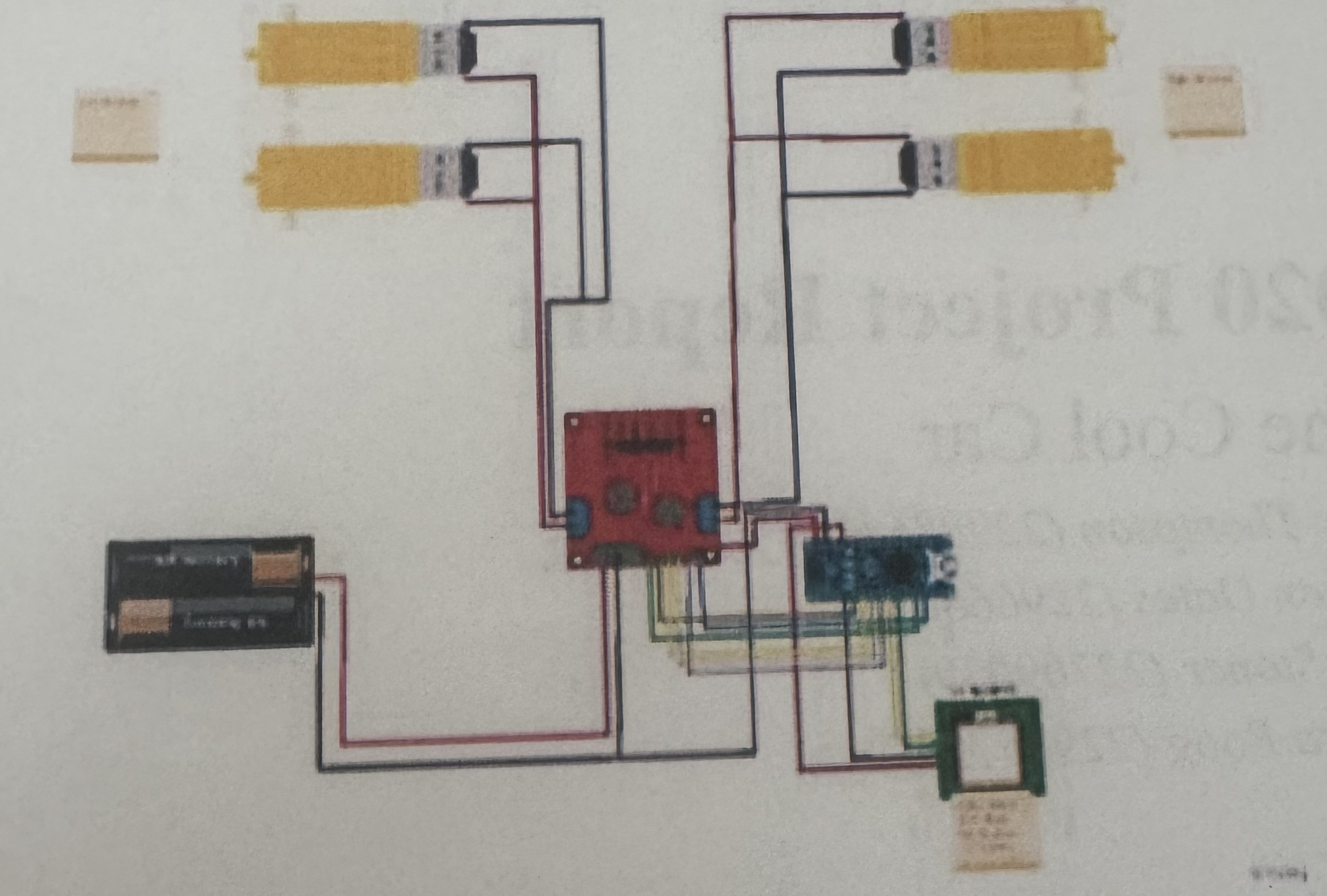
- Breakdown:
- A 12V power source is supplying power to the Vcc of the motor driver control module.
- The driver module controls two pairs of DC motors by using a H-Bridge.
- The module has a built-in 5V regulator which is then set to the 5V pin out to the Nano.
- Pins D2 through to D5 control in1:in4 and subsequently the direction of our DC motors.
- The GPS module is connected to the 5V and ground from the arduino and the RX and TX pins on the GPS module are connected to D6 and D7 on the arduino.
- The ground for the arduino is wired to the motor driver's voltage regulator, rather than a split wire (which is shown in the the diagram above.)
Software Design
- Designed to adjust the motor speeds depending on whether or not we are on track to the desired location.
- For example, if the desired location is slightly to the left, the left motors will slow down causing the car to turn left and vice versa for right.
- This was fine tuned so that the car drives in a reasonably smooth fashion.
- Program Breakdown:
- Define global variables:
- Arduino pins
- longitude and latitude
- The default serial connection was inefficient and disabled interrupts for a significant period of time (reference), so we switched to a community made library which improves on these limitations.
- Transitioned from tinyGPS to NeoGPS for more accuracy when working with shorter distances.
- We use a setup function to initialise all of our pins and the connection between the arduino and gps.
- We then have a loop function which is responsible for telling the car where to go.
- Distance (d) to desired location is found, along with the course to degree and the car's heading degree. (Refer to diagram below)
- The amount of change the car needs to make is calculated by taking the difference between the 2 angles and normalising this to within 360 degrees.
- This loop function has helper functions:
- One to get the desired location (user input)
- One to store the start location to return to
- Driving functions for the motors
- Define global variables:

Budget
| Name | Number | Quantity | Price (per) | Source |
|---|---|---|---|---|
| 8xAA 2 Rows of 4 Square Battery holder | PH9209 | 1 | $2.95 | JayCar |
| M/F M/M & F/F Cable Kit | N/A | 1 | $3.84 | Amazon |
| DIY Smart Car Chassis Kit 4 Wheel 2 layer robot smart car chassis kit with speed encoder for Arduino DIY | B08FLGNFY1 | 1 | $7.95 | Ali Express |
| Arudino Compatible Motor/Stepper Motor Controller Module | L298N | 1 | $10.95 | Aus Electronics |
| Duinotech GPS Receiver Module with On-Board Antenna | XC3710 | 1 | $13.75 | Core Electronics |
| TOTAL | 5 | $39.44 |
User Manual
Basic Usage
Intended to be used with the Arduino IDE (free download).
- Open code file.
- Declare the coordinates at the top of the file (global variable are there).
- LONGITUDE
- LATITUDE
- Connect your computer to the nano via appropriate cable.
- Click the arrow in the toolbar at the top of the arduino application to send the program (with your coordinates in it) to the nano.
- Quickly unplug your nano from the computer as the car will start driving after 5 seconds from sending the code to the Arduino nano.
Maintenance
- Runs on 8 AA batteries, if the car won't start or starts driving too slow, these will need changing.
- If any wires come out refer to the hardware circuit design or connections reference below.
Connections
- Arduino Nano to Stepper Motor Control Module:
- GND -> GND
- VIN -> 5V+
- D10 -> ENB
- D9 -> ENA
- D2 -> IN1
- D3 -> IN2
- D4 -> IN3
- D5 -> IN4
- Arduino Nano to GPS Module:
- GND -> GND
- 5V -> VCC
- D6 -> RXD
- D7 -> TXD
- Motor Servos to Stepper Motor Control Module:
- Left motors Power (Red) -> Right terminal of Motor B
- Left motors Ground (Black) -> Left terminal of Motor B
- Right motors Power (Red) -> Right terminal of Motor A
- Right motors Ground (Black) -> Left terminal of Motor A
- Battery Pack to Stepper Motor Control Module:
- Power (Red) -> VMS
- Ground (Black) -> GND